
close
Choose Your Site
Global
Social Media
Views: 0 Author: Site Editor Publish Time: 2026-07-07 Origin: Site


A PTO driven hydraulic pump serves as the heartbeat of mobile heavy equipment and agricultural machinery. When this vital component fails, it means immediate operational paralysis for your entire fleet. You simply cannot afford unexpected breakdowns in the middle of a critical job.
Improper sizing or component mismatch does not just break the equipment. It causes cascading downtime costs. Commercial fleets lose an average of $600 or more per day when trucks sit idle. Choosing the wrong unit drains your budget through emergency repair labor and missed project deadlines.
This guide provides a rigorous, engineering-backed framework for evaluating, sizing, and implementing PTO systems. We shift the focus from upfront unit price to long-term reliability and operational lifespan. You will learn how to select correct components, dodge common matching mistakes, and ensure your machinery runs efficiently under heavy loads.
Always apply a 10–15% safety buffer to peak flow and torque requirements, especially to accommodate winter oil viscosity fluctuations.
Continuous duty cycles (exceeding 5 minutes or running over 2000 RPM) require a mandatory 30% derating of published PTO torque and horsepower limits.
Fluid contamination causes up to 80% of hydraulic failures; proper reservoir sizing (2–3x GPM) and return filtration (1.5x system flow) are non-negotiable.
Clutch-dependent vs. clutch-independent applications dictate exact mounting configurations (rear, side, or engine-mounted REPTO).
Budgeting solely on the initial pump cost ignores the high risk of mechanical linkage failure and equipment downtime; premium components offer a 6–10 year lifespan compared to 1–2 years for budget alternatives.
Selecting the right configuration starts by analyzing your specific vehicle operations. You must frame a fundamental decision tree based on whether your machinery operates statically or on the move.
Your vehicle's movement status dictates the type of PTO engagement required. We generally divide these into two distinct categories:
Clutch Dependent PTOs: These setups require the vehicle to remain completely stationary. The operator must depress the clutch to engage the gears safely. We typically see this configuration in dump trucks and heavy lift cranes. They need massive power bursts, but only when securely parked.
Clutch Independent PTOs / REPTO (Engine Mounted): These configurations allow continuous operation while the vehicle moves. They draw power directly from the engine. You need them for concrete mixers, snowplows, and refuse collection vehicles. Without independence, a concrete mixer would stop spinning every time the driver shifted gears.
Physical clearances underneath your chassis heavily influence mounting strategies. You must measure the available spatial footprint before buying parts.
Side Mount: This configuration works best for snowplows and dump trucks. These vehicles often require specific spatial clearances to avoid interfering with bulky exhaust systems or frame rails.
Rear Mount: We prefer rear mounts for continuous heavy-load systems. Vacuum trucks and industrial blowers rely on them extensively. While they handle high torque better, they present unique plumbing challenges. A rear mount often requires remote fluid reservoirs and boosted inlets to prevent damaging cavitation.
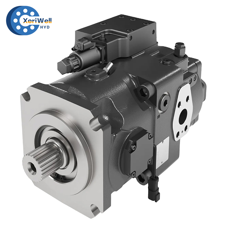
You must map your application demands directly to specific pump types. Gear designs provide high reliability and low initial cost. They handle standard agricultural operations perfectly. Piston designs step in for variable, extreme high-pressure applications. When lifting massive loads, a premium hydraulic pump ensures exact fluid control. Piston units adjust flow dynamically, saving fuel and reducing dangerous heat buildup.
Guesswork leads to catastrophic system failures. Using standard industrial math builds authoritative trust and protects your investment. You must calculate absolute minimum requirements before finalizing any purchase.
We rely on two core sizing formulas to establish baseline performance metrics. The constant numbers represent standard unit conversions used by engineers globally.
Hydraulic Horsepower requirement: HP = (GPM × PSI) ÷ 1,714
Corresponding PTO Torque: Torque (lb.ft.) = (HP × 5,252) ÷ RPM
These equations define your power floor. They ensure the transmission output matches the fluid power demand.
You must distinguish clearly between intermittent and continuous loads. Intermittent loads offer brief power bursts followed by cooling periods. Continuous loads sustain pressure over longer durations.
The industry follows a strict derating rule. If a system operates under maximum load for more than 5 minutes within a 15-minute window, it is continuous. Similarly, if it exceeds 2000 RPM at any time, it is continuous. In these exact scenarios, buyers must reduce the PTO's published torque and horsepower ratings by 30%. This mandatory buffer prevents premature mechanical fatigue and protects gear teeth from shattering under sustained stress.
Heavy-duty continuous applications require enterprise-grade components. Buyers frequently evaluate premium options to guarantee maximum uptime. Comparing your calculated specifications against established industry standards helps secure a safe baseline.
For example, referencing the performance curves of a DANFOSS Hydraulic Pump or a REXROTH Hydraulic Pump provides vital clarity. It helps you verify the required volumetric and mechanical efficiency limits. These benchmarks prevent you from under-sizing critical components, ensuring robust architecture for demanding environments.
Even perfectly calculated systems fail if integration steps are ignored. Pay close attention to these four common installation errors.
Mismatched gear ratios destroy internal components quickly. Unfavorable ratios over-speed the internal gears beyond their design limits. This causes extreme friction and heat generation. High temperatures lead to rapid fluid degradation, breaking down protective oil viscosity. Consequently, you experience accelerated bearing wear. Always verify transmission output ratios against the pump's maximum RPM limits before installation.
Operators frequently engage the system under heavy load or at high engine RPM. This causes severe mechanical damage. The sudden shockload shatters gear teeth and shears splines instantly. Smooth, low-RPM engagement is strictly required. Easing into operation protects clutches, internal gears, and expensive drive shafts from impact fractures.
Undersized tanks cause silent system death. They prevent proper fluid cooling and block natural deaeration. Trapped air bubbles implode under pressure, physically pitting internal metal surfaces. You must establish strict volume rules.
Reservoir capacity must equal 2 to 3 times the pump’s GPM rating.
Return filters need a minimum rating of 1.5 times the system's peak flow.
Keep suction lines short and straight to prevent fluid starvation.
Mechanical drives require straight alignments to function properly. Using mechanical driveline shafts at excessive offset angles destroys components. We see this frequently in ditch mowing or offset agricultural implements. These applications force the driveline into severe angles. The rotational strain literally tears U-joints apart. Keep operating angles as shallow as possible.
Evaluating purely on initial price tags leads to terrible business decisions. You must weigh upfront costs against long-term operational lifespan to calculate true return on investment.
The budget market pushes units in the $350 to $600 range. These cheap alternatives usually last only 1 to 2 years before seals fail or casings crack. Conversely, heavy-duty commercial-grade units cost $1,500 or more. However, they deliver a robust 6 to 10 year lifespan under grueling conditions.
Downtime penalties expose your actual financial risk. Commercial fleets face an average loss of $600 per day when a truck sits idle in the shop. A single failure of a budget unit easily eclipses any initial procurement savings. You lose thousands of dollars in missed revenue. Furthermore, emergency repair labor rates drain fleet profits aggressively.
We guide buyers to select equipment based strictly on duty cycles. Use the matrix below to evaluate your true operational needs.
Duty Cycle Category | Typical Applications | Recommended Setup | Expected Lifespan |
|---|---|---|---|
Low-Use / Seasonal | Small farm tractors, log splitters | Standard aluminum gear unit | 1–3 Years |
Medium-Use / Intermittent | Local dump trucks, light cranes | Cast iron gear unit | 3–5 Years |
Heavy-Use / Continuous | Refuse fleets, vacuum trucks, snowplows | Premium piston high-torque unit | 6–10 Years |
Precise installation separates reliable fleets from constantly failing ones. Mechanics must respect strict engineering tolerances during assembly.
Gear backlash adjustments determine transmission survival. You typically adjust backlash clearances between .006” and .012” using precision mounting shims. Listen closely during initial testing runs.
A high-pitched whining sound indicates a fit that is too tight.
A metallic clattering sound means the fit is too loose.
Both scenarios cause rapid component failure. Mechanics must adjust shims until the mesh sounds smooth.
Torsional resonance prevention requires careful calculation. Driveline-driven setups must meet strict OEM compliance requirements. Volvo, for instance, publishes rigorous specifications regarding harmonic vibrations. Driveline systems must be engineered so the minimum torsional resonance frequency sits safely above 300 Hz. Ignoring this rule causes catastrophic engine harmonic damage, literally shaking engine blocks apart over time.
Troubleshooting early failure signs saves fleets immense money. Train operators to watch for these three primary indicators:
Slowed cylinder operation or erratic pressure: This usually points directly to internal casing wear or fluid cavitation.
Spontaneous disengagement or high operating temperatures: These symptoms point to binding mechanical linkage issues or burning solenoid failures.
Metal flakes in the hydraulic fluid: This acts as a terminal warning. It requires an immediate system shutdown and a full fluid flush to save downstream valves.
Successful procurement requires balancing multiple technical variables. You must match flow and pressure needs perfectly. Vehicle transmission compatibility is not optional, and duty cycle realities dictate your final selection.
We advise buyers to conduct a full machinery audit today. Measure your current reservoir capacities accurately. Document your real-world operational duty cycles. Complete these steps before requesting quotes or finalizing specifications. Taking a proactive approach ensures your equipment remains highly productive for years.
A: You must apply a 10-15% sizing buffer to your peak flow and torque requirements. Cold weather significantly increases fluid viscosity, making oil thicker and harder to move. This buffer ensures adequate power delivery without stalling the system when temperatures drop.
A: A direct-mount connects directly to the PTO housing via an internal spline, saving space and eliminating exposed moving parts. A remote-mount uses a secondary driveline or shaft to connect. Remote mounts help bypass tight chassis clearances but require careful alignment.
A: Yes, but you must adhere to the 30% derating rule. If operating beyond 5 minutes or over 2000 RPM, reduce published torque and horsepower limits by 30%. You must also integrate external oil coolers to manage the immense heat generation.
A: A high-pitched whine typically indicates that gear backlash adjustments are too tight. It can also point to severe aeration or fluid cavitation forming in the suction line. Both issues require immediate mechanical inspection to prevent internal destruction.


